_Ogre
we received the 4x8 turnkey plasma table last week. i will document the set up and run off here.
_Ogre
first off. no instructions, no documentation.
where do i find manuals? are they in the pc?
where does the thc sensor pmw hook too?
it came in a bag with a plug that matches the cpc port on the powermax 65.
the dcp port looks like a phone cable and there is a ethernet port on the side.
there is an ethernet cable in the box.
what does it plug into?
[URL=http://s306.photobucket.com/user/_ogre/media/Misc/Plasma/1220131518_zps0e579062.jpg.html][IMG]http://i306.photobucket.com/albums/nn255/_ogre/Misc/Plasma/1220131518_zps0e579062.jpg[/IMG][/URL]
[URL=http://s306.photobucket.com/user/_ogre/media/Misc/Plasma/1220131517_zps5993d53b.jpg.html][IMG]http://i306.photobucket.com/albums/nn255/_ogre/Misc/Plasma/1220131517_zps5993d53b.jpg[/IMG][/URL]
i have 2 cables: 'A' from the rotary table i assume plugs into the 'A' port on the control box.
also a cable marked 'B' does this go into the 'HW slave' port? the only available plug.
[URL=http://s306.photobucket.com/user/_ogre/media/Misc/Plasma/1220131521_zpsd310ff5b.jpg.html][IMG]http://i306.photobucket.com/albums/nn255/_ogre/Misc/Plasma/1220131521_zpsd310ff5b.jpg[/IMG][/URL]
[URL=http://s306.photobucket.com/user/_ogre/media/Misc/Plasma/1220131522_zps63da5221.jpg.html][IMG]http://i306.photobucket.com/albums/nn255/_ogre/Misc/Plasma/1220131522_zps63da5221.jpg[/IMG][/URL]
_Ogre
how close can the powermax65 and the pc be located? same table/bench/cart? 5 ft away?
can the plasma cable and the control cables; serial and printer cables, be run together without causing interference?
got the rotary table mounted today. have no chuck key for the chuck, can you send us one?
jeepsr4ever
There should have been some videos on the desktop. A goes to A axis and B to the Aux. There is also support files on the desktop. Ethernet connects to PWM to big black box and does not go to the PC. DCP is not required and you have the two cables hooked up correctly. They can all run together no problems. The plasma should be at least 3 feet away from the big control box. Thats great you got the rotary table mounted! They are very heavy!
_Ogre
after posting those i found the manual on the cancnc site. that explained most everything.
also found all the manuals on the pc that i hadn't hooked up yet.
got all motors to jog today. baby steps.
rotary table is heavy for sure
bearings look like could be for a battle ship prop shaft.
_Ogre
just did a test of our new bulltear 4x8 w/ dthc, mach3 bladerunner and powermax 65. the torch fired and cut the shapes i had drawn; just out of scale. i am fairly well versed in autocad 2000 and use it for all technical drawings the drawing is in inches. i had drawn simple shapes ''plasma test'' 2- 2'' circles and 2- 2'' squares and an arc thingy. the circles and squares cut great, they were just 4.5'' across instead of 2'' as drawn. any ideas of what i did wrong?
plasma test
[url=http://s306.photobucket.com/user/_ogre/media/Misc/Plasma/plasmatestModel1copy_zps01d51beb.jpg.html][img]http://i306.photobucket.com/albums/nn255/_ogre/Misc/Plasma/plasmatestModel1copy_zps01d51beb.jpg[/img][/url]
this might be a sheetcam tng problem but i'll post it here too:
so i moved on to my first real project. ''mrt bronco3'' is a couple of simple signs to be cut out of 10 ga mild steel. it took me a few times to get all of the arcs drawn to make 1 pierce per letter, when i run sheetcam it has the outside of one sign cut first then the letters. then sheetcam jumps around cutting some letters in the 2nd sign then some letters in the 3rd sign, then the outside of one sign and then the rest of the letters. how do i move pierce point and the layout of the cuts?
plus i'm a little leery of cutting these out until i get the scale thing figured out.
mrt bronco3
[url=http://s306.photobucket.com/user/_ogre/media/Misc/Plasma/mrtbronco3Model1copy_zps88ce9cdf.jpg.html][img]http://i306.photobucket.com/albums/nn255/_ogre/Misc/Plasma/mrtbronco3Model1copy_zps88ce9cdf.jpg[/img][/url]
also can any one tell me how to do a test draw? or test the cut path without the torch on?
i tried to run the gcode in mach3 with the torch off and z axis zeroed out one half inch above the water table slats. the z axis went past zero and traveled below the slat surface.
_Ogre
received the software disc and the thumb drive. thanks for the backup files.
what files do i need to back up to save all the profiles that the machine came loaded with?
one last thing today; how do i use the play station controller?
i have it plugged into a usb port but it controls no motion at this point.
jeepsr4ever
If your cutting oversize a setting is off. Call in when you can someone here will take care of it for you. You should be next to the PC with Mach running.
_Ogre
thanks for the phone setup help mc. ran the test piece to the correct scale after that.
what files do i need to back up to keep those settings?
the game controller makes life easy peasy too. nice jog/start/stop functionality.
i've read everything in the forum for setting up the table, there's not much on the rotary head.
want to try that out next. can you send me some links or info on the rotary head?
also any way to dry cycle the machine? test run on pieces with out the torch on.
jeepsr4ever
XML file in Mach3 called Bladerunner and Bladerunner rotary. Dry run with plasma off by pressing torch on/off after initial touch off. Rotary is setup to use no limits or home switches. More soon!
_Ogre
tried the rotary head today with out any luck. loaded a cope program in the rotary mach3 program. the y axis took off, y axis should be centered on the tube and all cutting done with x and a axis. tried the tube cut program y axis took off again. so quit that and left you a voice mail. i'll try to call bulltear on monday.
on the plus side... table is working well. cut the mrtbronco4 door roll bar signs and a receiver mounted 3rd brake light cover for the 66 bronco we have in the shop. also cut out some hole test and line test drawings. everything working well. thumbs up on this table. :D
mrtbronco4
[URL=http://s306.photobucket.com/user/_ogre/media/Misc/Plasma/mrtbronco3Model1copy_zps88ce9cdf.jpg.html][IMG]http://i306.photobucket.com/albums/nn255/_ogre/Misc/Plasma/mrtbronco3Model1copy_zps88ce9cdf.jpg[/IMG][/URL]
line test (drawing not to scale)
[URL=http://s306.photobucket.com/user/_ogre/media/Misc/Plasma/0104141336_zps400c0a42.jpg.html][IMG]http://i306.photobucket.com/albums/nn255/_ogre/Misc/Plasma/0104141336_zps400c0a42.jpg[/IMG][/URL]
hole test (drawing not to scale)
[URL=http://s306.photobucket.com/user/_ogre/media/Misc/Plasma/0104141333_zps56577548.jpg.html][IMG]http://i306.photobucket.com/albums/nn255/_ogre/Misc/Plasma/0104141333_zps56577548.jpg[/IMG][/URL]
did some testing on cutting holes in 16 ga 304 stainless exhaust tube just using the x,y,z axis's and the dthc with moderate success.
this is for welding in the H on an H pipe exhaust; normally we'd use a 2.25'' hole saw at $12 per for maybe 10 holes (5 systems)
had to use settings for 10 ga steel to complete the cuts down low. lots of dross, but it's easy to clean off.
the holes are 2.25''x1.75'' elliptical
[URL=http://s306.photobucket.com/user/_ogre/media/Misc/Plasma/0104141424_zps5fd5538f.jpg.html][IMG]http://i306.photobucket.com/albums/nn255/_ogre/Misc/Plasma/0104141424_zps5fd5538f.jpg[/IMG][/URL]
[URL=http://s306.photobucket.com/user/_ogre/media/Misc/Plasma/0104141423_zps7dbba571.jpg.html][IMG]http://i306.photobucket.com/albums/nn255/_ogre/Misc/Plasma/0104141423_zps7dbba571.jpg[/IMG][/URL]
hoping to get the rotary head going on monday to cut out the actual H pieces
[URL=http://s306.photobucket.com/user/_ogre/media/Misc/Plasma/0820131316_zps504692b3.jpg.html][IMG]http://i306.photobucket.com/albums/nn255/_ogre/Misc/Plasma/0820131316_zps504692b3.jpg[/IMG][/URL]
[URL=http://s306.photobucket.com/user/_ogre/media/Misc/Plasma/0820131449_zps5489999f.jpg.html][IMG]http://i306.photobucket.com/albums/nn255/_ogre/Misc/Plasma/0820131449_zps5489999f.jpg[/IMG][/URL]
jeepsr4ever
We may not be open on Monday. To use the rotary you must first open the rotary button and not the bladerunner button. Our weather is going to be in the 30s below zero and our state governor shut down all public schools. This means no workers. I may be in briefly so leave me a message.
_Ogre
the cold weather is headed our way too. had to leave the water running or we lose water in the shop around zero.
i used the rotary program. probably a setup issue to lock out y axis. i did not find any info on the rotary program in on the mach3 website or in the mach3 manual. i had to manually load the pierce height in the setup tab. i entered the tube diameter in the main screen and zeroed z axis on the tube surface. is there any documentation for the tube program?
jeepsr4ever
If you check the setup area and there should be a blurb on it from your desktop (Setup rotary). If Y axis is moving then we most likely have to toggle the outputs in Config/ports and pins and make sure the X is moving for Y movements for rotary only(But I don't believe that is ever setup wrong). The A axis and X axis move the gantry down the long travel. The A axis is hardware slaved to the X axis which is unique to rotary cutting machines only. So if Y is moving we need to verify the output for rotational movements are not outputting to Y BUT my suspicion is that the interface for testing it looking for a Y axis limit switch. So if you go through to the final test you can opt out of finding the limit for calculating diameter through the test button. This opts out of looking for a Y axis limit switch. The reason we don't use the Y axis home switch for rotational machines is because you can mount it anywhere and often it will not be parallel to the X axis.
jeepsr4ever
Rotary also requires attention paid to acceleration rates. So when you get your tube diameter and go halfway through the test you need to go into the config/motor tuning and see what A axis says for acceleration. The deal is that if all axis are not tuned to the same acceleration rate your cut geometry will not be accurate. So you will need to change the X axis to the same acceleration as the A axis. Often times the wizard will drop acceleration so low it doesn't work well with THC on. Tweaking the acceleration to a usable number with THC will allow you great cuts. At a 2" to 2.5" diameter that should not be a problem. The ratio is 21-1 on the rotary so the max cutting speed on a 2" diameter is around 200ipm and less as the diameter decreases.
_Ogre
not sure how to ground the rotary head, i assume grounding to the table would weld the bearings in the rotary head.
similar to welding on a rearend with the ground clamp on the bumper
this is the interface i'm dealing with (image borrowed from the internet)
i have the round pipe/tube active, diameter set for 2.55''.
though instead of the calculate/touchoff/setup buttons on the right,
there is a tube cutoff function that you set the length and number of pieces.
the rotary read out does not change as the head rotates either
[IMG]http://www.candcnc.com/images/MP3000_DTHC-Rotary2.png[/IMG]
jeepsr4ever
If the rotary doesn't move then its mapped wrong. You can go to config/ports and pins/Motor outputs and map A axis the same as B axis.
jeepsr4ever
[SIZE=5][COLOR=#0000ff]My guess is your not using the Rotary post processor in sheetcam.[/COLOR][/SIZE]
_Ogre
no, i wasn't using the rotary post processor. am now
but when i do it swaps the axis's. i did a tube cutoff and instead it slit the tube lengthwise.
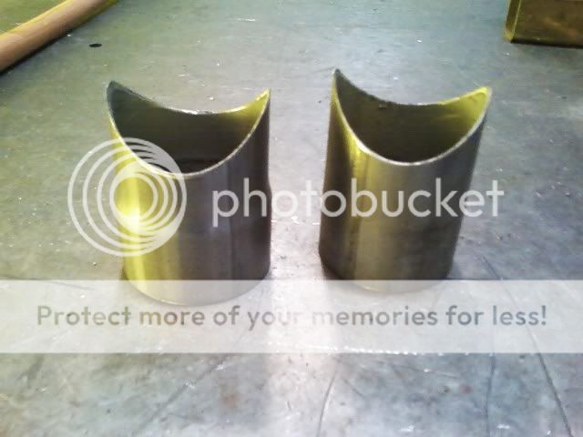
i rotated the dxf in sheetcam -90* and it cut semi correctly.
the dxf line is 7.96'' long, which is the same as the circumference of the 2.54 tube
but the straight line cut lacks 5/8'' of cutting the tube. is this more motor tuning issues?
[URL=http://s306.photobucket.com/user/_ogre/media/Misc/Plasma/0106141429_zps565dfdcf.jpg.html][IMG]http://i306.photobucket.com/albums/nn255/_ogre/Misc/Plasma/0106141429_zps565dfdcf.jpg[/IMG][/URL]
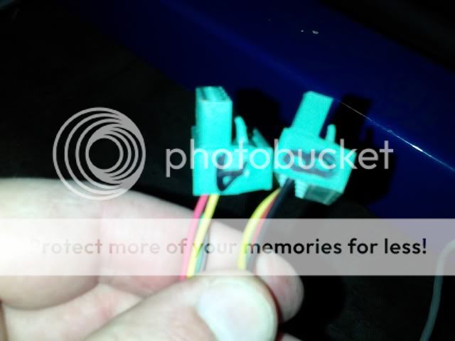
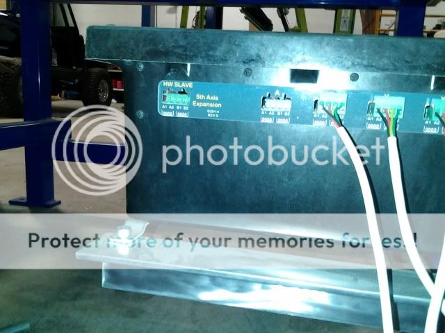
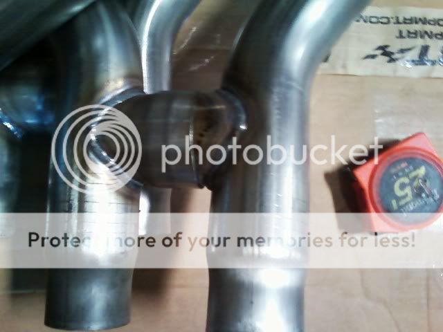
back on the axis swap issue with x and a axis and not rotating enough.
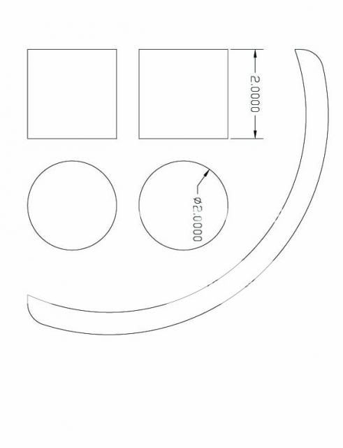
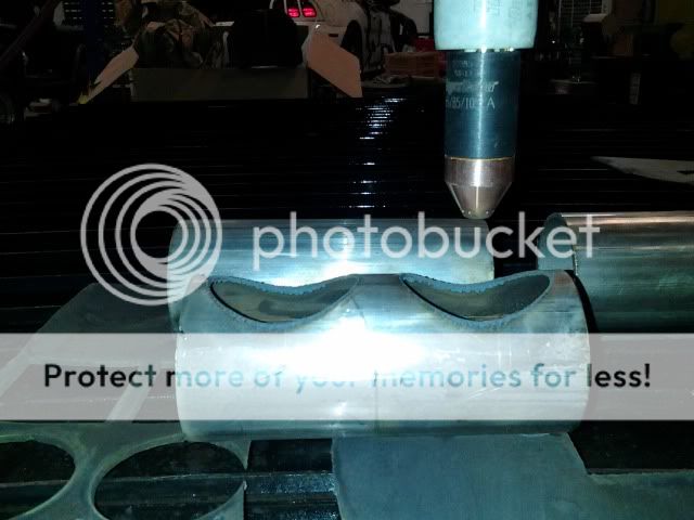
i cut a circle out of 2.5'' tubing and it cut as an oval, not enough rotation again
also the cut should have started on the left of this picture instead it started at the top where the torch is.
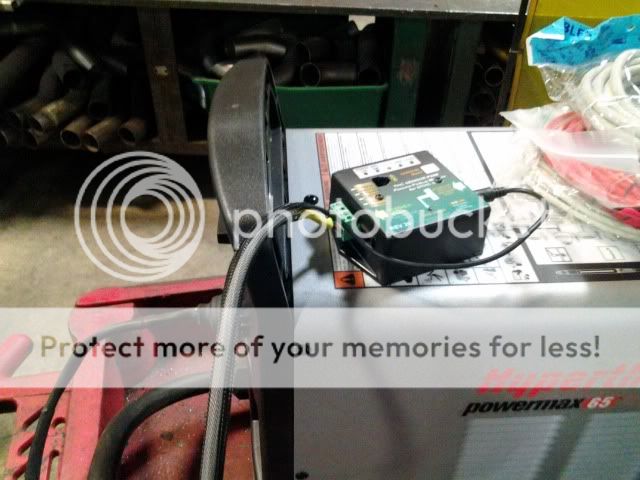
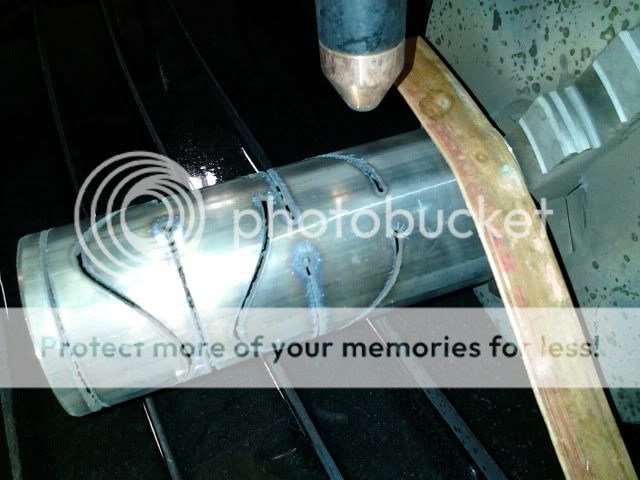
notice my ground strap. 1/2'' copper tubing hammered flat and clamped to the side of the water table with the ground clamp.
[URL=http://s306.photobucket.com/user/_ogre/media/Misc/Plasma/0106141348_zps726c37f7.jpg.html][IMG]http://i306.photobucket.com/albums/nn255/_ogre/Misc/Plasma/0106141348_zps726c37f7.jpg[/IMG][/URL]
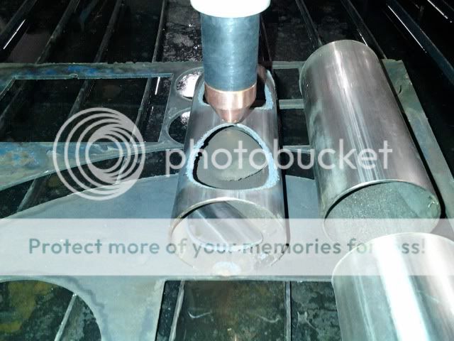
also want your opinion on the chuck location; should it be over the water like this
water splash is already rusting the chuck and makes that end of the table of limited use.
[URL=http://s306.photobucket.com/user/_ogre/media/Misc/Plasma/0106141500_zps3da7418e.jpg.html][IMG]http://i306.photobucket.com/albums/nn255/_ogre/Misc/Plasma/0106141500_zps3da7418e.jpg[/IMG][/URL]
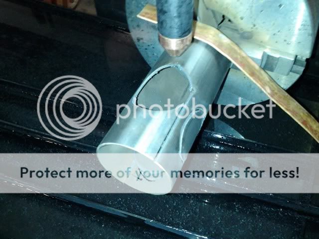
the dthc needs some tweaking too.
for some reason the torch is diving and hanging on the rotating tube and x axis movement.
the cuts above were done with the dthc off, with the dthc on the hole is G shaped
will call you in the morning, just wanted to post these pictures so we could discuss them tomorrow
jeepsr4ever
I will check out the numbers for reduction (It is either that or your loosing steps in the rotary motor (shouldn't be the case) or your lines aren't long enough (DXF)). Also with a chuck mounted you may never get full travel it just doesn't work that way with rotary cutting and sheet cutting. You could modify the mount to sit back further but that limits short piece cutting. There are a couple of ways to deal with running a full sheet. One is to take the chuck off the shaft by removing the 4 3/8 bolts and the other is taking the whole rotary off. You probably loose 1-2"s of travel in 99"s so theoretically maybe an inch of travel if that. If you move your gantry all the way back how much travel do you loose?