Setup instructions for 5x10 BTA plasma gantry kit (**MECHANICAL)
Part list
End plate (assembled) X2
Z axis (assembled with limit switch)
Gantry rail
Long axis rail X2
Control head
4 motors (one lead is longer than the other 3)
DTHC card
3 gears
long cable track (with 2 sets of bolt plates)
Msc bolts, cables
First make sure you have adequite room for assembly. This assembly will require some fabrication. The fabrication can be done exactly how we do it in our build area or any other way.
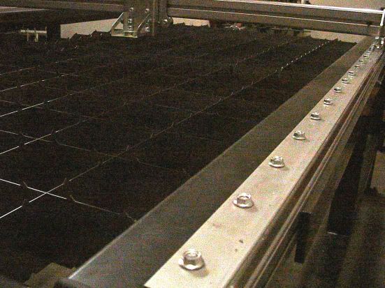
BOLTING SLATS TO SUPPORT TABLE
Bolting the slats can be a quick easy job or can take a little bit of tweaking. The first thing you must know is that the V wheels must ride on the peak of the V rail. They must be lined up perfectly. This is done by measuring the width of the Gantry with the end plates bolted on the gantry. Measure from V to V and note this measurement.
Now you will need a couple of clamps (at least 4) to clamp the rail on your support table and measure before you bolt it down. Carefully clamp the 2 V rails on the support table sides. Measure one end between both V rails it should be right at the measurement you had between V wheels on the gantry. If it isnt at the measurement then you will need to move the V rail (It is very common to have V rail offset from support table tubing). Drill 3/16 and table 1/4-20 threads on the very end bolt and bolt both sides to support tube. (support tubes are the tubes that bolt to your support table and hold the V rail on top, these are not supplied but a print of them should be)
Moving 10 holes down measure the width again and repeat until you have bolt rails bolted down. If for any reason you are worried about the width you can install the gantry on the rails while the rails are clamped on to ensure proper width.
If you have an issue where one fo the V wheels is riding up you can loosen the bolts on the V rail and if that isnt enough you can use the small adjustment on the end plates by moving the jam nut and moving the V wheel.
Install the Z axis if you havent already by taking an endplate off and sliding the Z axis using the V wheels and V ribs. If you find the Z axis sloppy you can add pre-load by loosening one fo the V wheels and turning one of the cam bolts behind 2 of the V wheels. Make sure you re-tighten the wheels if you needed to preload.
[b]******GANTRY IS INSTALLED******[/b]
MOTORS
Take your motors out and measure the leads on them. Make sure you can find the motor with the longest lead and the other three should be shorter but equal length
Take the motors and install the gears without tightening the setscrew (2-1 reduction units are set differently, install the motor on the 2-1 reduction unit. The 2-1 reduction unit will have a slight press fit gear, this is so you can move the gear to at least 80% contact and use a couple drops of loctite 294 to keep gear in position *(294 requires 24hr set time))
Install the motors on the end plates in the long axis (long axis has 2 motors one is driving in reverse and is slaved) **we will call this the X axis ***note that the long axis will use on motor with the longer lead, this lead can go through the center hole of the gantry but the plug on the end of the wire must be removed to fish it through the hole then the plug can be screwed back on. Make sure you put the wires in the correct position on the plug after fishing the wire through. You can use the other motors as a reference.
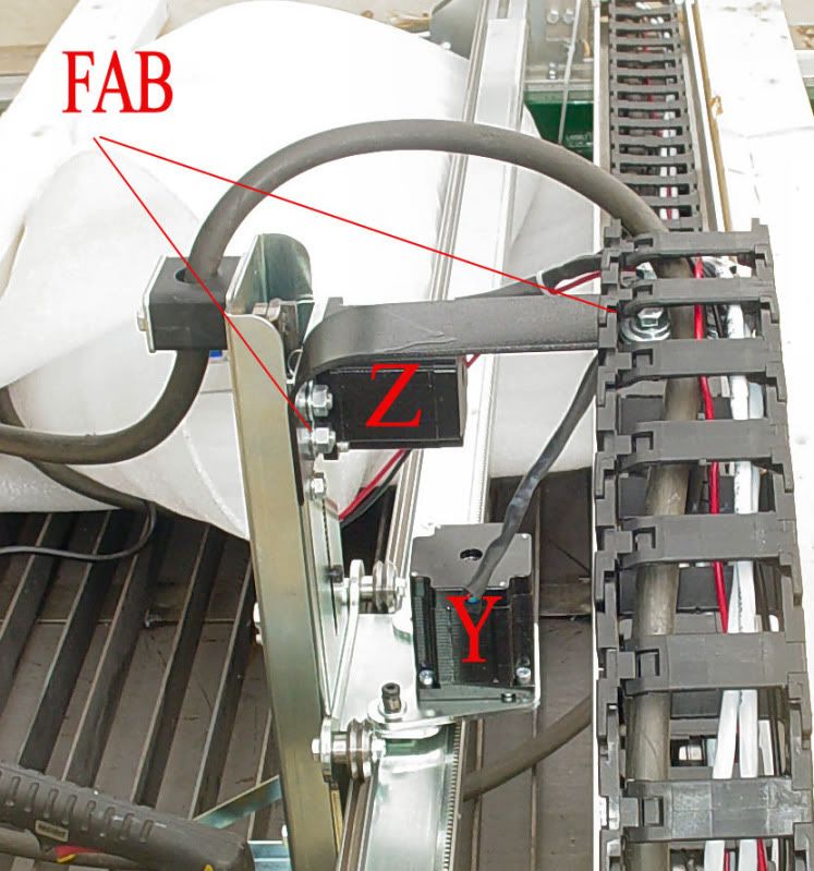
Y axis motor is to be installed on the Z axis housing in the back, the Y axis actually runs the Z axis carraige from side to side. (2-2 reduction units must check gear contact *80% contact at least and then use 294 loctite drops ion the end of gear **294 is wicking and will seep into the mating surfaces)
Z axis motor has a small gear attached to it and then is bolted into the Z axis (axis runs torch head up and down) **check gear and make sure gear end does not contact V rail inside Z axis head. Then tighten the setscrew on the Z axis.
****MOTORS ARE INSTALLED ON GANTRY****
CABLE CARRIER
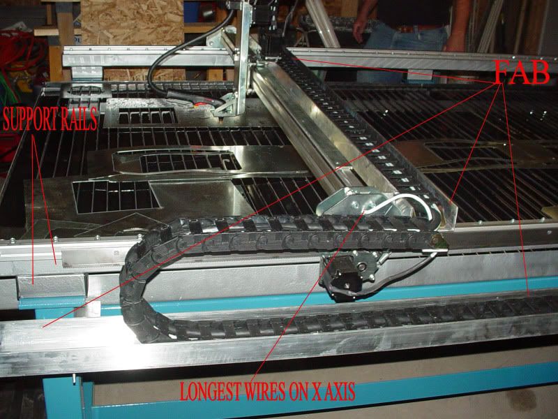
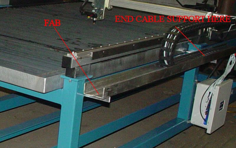
Cable carrier is the best way to hold your plasma lead and your motor leads. Our 5x10 kits will come with cable carrier however some fabrication will have to be done. This fabrication will be the support for the cable carrier.
Take cable carrier and the 2 sets of brackets. A set of brackets consists of a start and an end for the cable carrier. One length of cable carrier will span the gantry and the other length will span half of one side of the X axis or long axis. The tables are setup for mounting the control head in the middle on the support table on the side under the support tube. Bolt on brackets should have been supplied for the control head (you will need to drill and tap to support the control head)
The gantry cable carrier will need 2 brackets made and a couple of holes drilled. This is the cable carrier support made out of C-channel aluminum. The support doesnt have to be C-channel it can be flat because the cable carrier will always fold in strait lines.
Note here